Infrastructure Built for What's Next
Two integrated service lines, engineered to serve the most demanding digital workloads on the planet, deployed across India's most strategic locations.
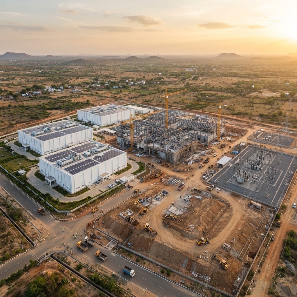
Build to Suit
We design and deliver purpose-built, AI-ready data center campuses tailored to your technical, operational and commercial requirements, from free-scale 50 MW buildings to giga-scale 1 GW+ ecosystems. Our full-lifecycle model spans site acquisition, energy planning, design and engineering, construction and data-driven operations, backed by renewable energy and energy-as-a-service.
- Free-scale, mega-scale and giga-scale delivery models, up to 1 GW+ ecosystems
- Full lifecycle ownership: site acquisition, energy planning, design, build, operate
- Energy-as-a-service: solar/wind generation, private transmission, on-site microgrids
- AI-ready, future-proof design with programmable whitespace and hardware-agnostic flexibility
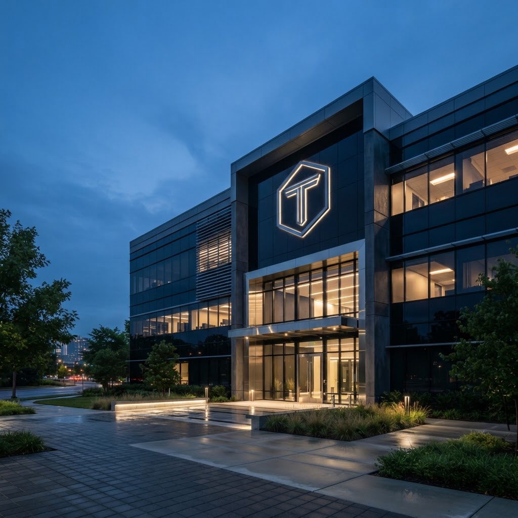
Colocation
Carrier-neutral colocation engineered for the full spectrum of workloads, from Colo+ cabinets to dedicated cages and private suites. Flexible power densities from 3 kVA to 300 kW per rack, precision cooling, biometric dual-authentication security and 24×7 remote-hands support, all monitored through our DCIM platform.
- Colo+, dedicated cages and private suites for CPU and GPU workloads
- Flexible power densities from 3 kVA to 300 kW+ per rack
- Dual PDUs, fiber/copper cross-connects and biometric dual-authentication security
- Carrier-neutral meet-me room with 60+ network providers
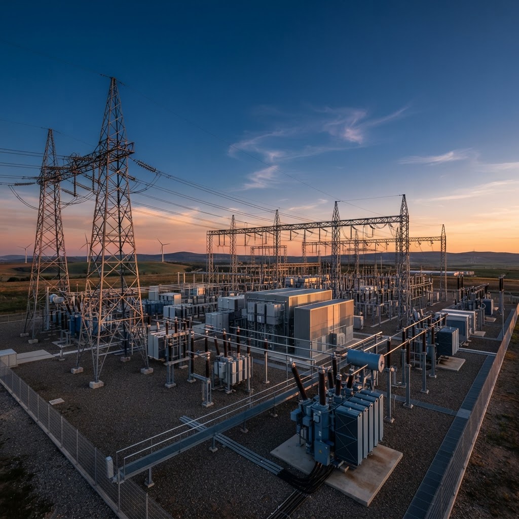
400 kV × 2 / 220 kV
Two independent grid sources, with a 220 kV interim bridge
Every campus is planned around a 400 kV connection from two independent sources, with both the central (CTU) and state (STU) transmission routes kept open. Early phases energise on a faster 220 kV interim supply while the full-build connection is completed.
One platform, sized for the way you buy capacity
Hyperscalers buy in campuses and availability zones. AI clouds buy in pods and need them energised fast. TeraNova's standard pod-floor-building template serves both from the same land, power and supply chain.
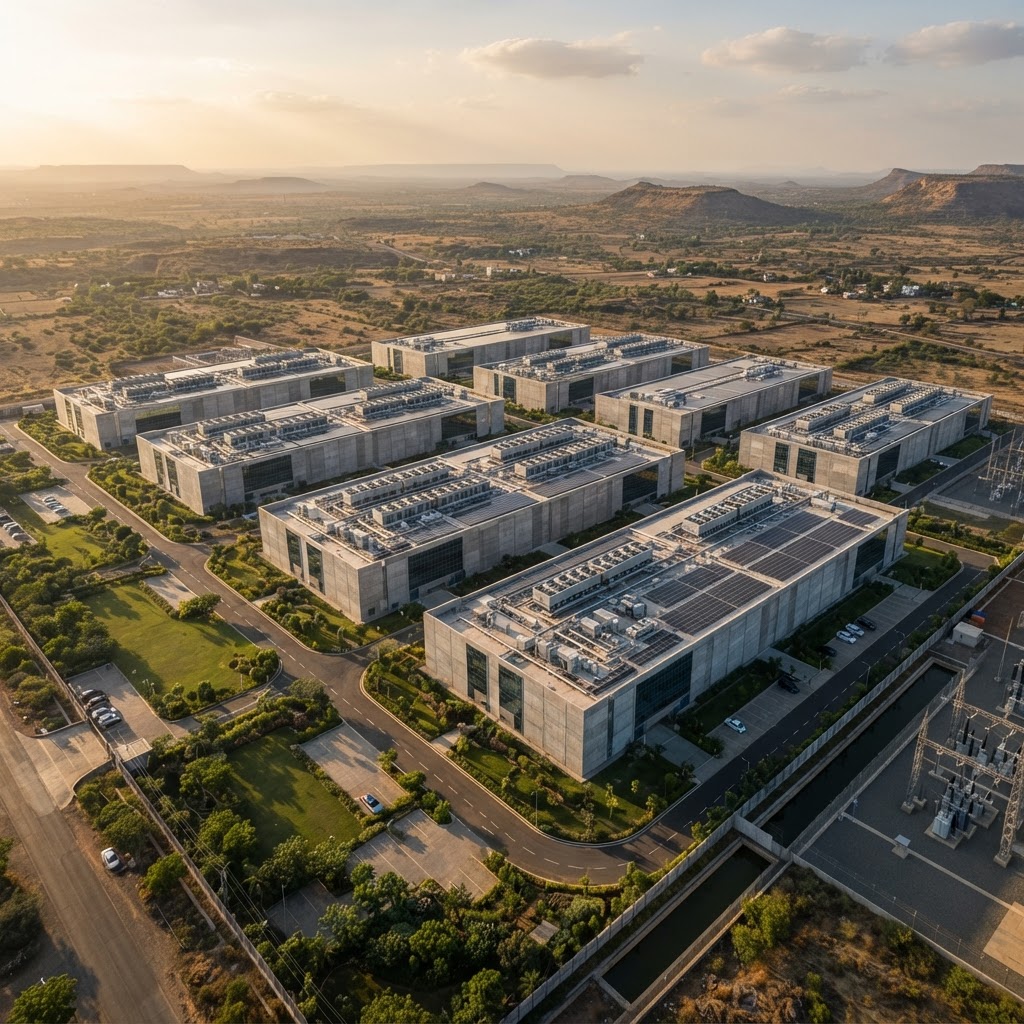
Campus-scale capacity to your standard
- 108–150 MW buildings on 48 to 170-acre campuses, at 22–25 MW of IT per acre
- Multi-parcel clusters in Mumbai and Hyderabad, planned as availability zones within metro distance
- We build to your basis of design and reference architecture, with no redesign between variants
- Two independent 400 kV sources per campus, with CTU and STU routes both kept open
- Renewable supply structured for 100% RE commitments through inter-state open access
- Powered land, powered shell, build-to-suit or BOT, with long-tenor certainty

GPU-ready pods, energised on your ramp
- Start with a single 2.2–2.5 MW pod and add pods as contracts land, with no idle capex
- Structure, cooling and power sized for GB300 today and Vera Rubin next
- 42 kW air-cooled to 160 kW liquid-cooled per rack, with CDU power and manifolds pre-laid
- OCP Open Rack V3 (21", 48 VDC) envelope with AC + DC hybrid per pod
- Adjacent pods handed over four weeks apart; new pods hot-tied without shutting live halls
- India-resident capacity for sovereign AI and data-residency workloads, run by a 24x7 NOC
Five ways to take capacity
Choose how much TeraNova delivers and how much you own. Every model sits on the same entitled land, the same grid connection and the same tested building template, so you can start with one model and move to another as your programme grows.
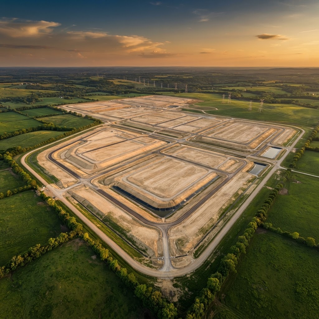
Entitled land with a path to power
Clear-title industrial land with zoning, statutory approvals, power sanction and the EHV route in hand. You design and build.
Hyperscalers running their own design and construction programmes
Core, shell and power to the building
A GPU-grade structure (2,500 kg/m², 7 m+ clear) with substation, MV supply and site utilities delivered. You fit out the halls.
Hyperscalers with a standard in-house MEP fit-out
Turnkey to your specification
We design, procure, build and commission a facility to your basis of design, then lease it to you long term. Operations by you or by us.
Hyperscalers who want capex-light capacity built to their own standard
We build and run it, then hand it over
TeraNova delivers and operates the facility under SLA for an agreed period, trains your team, and transfers ownership on agreed terms.
Platforms and sovereign programmes that want eventual ownership with delivery risk carried by us
Ready-to-fit pods, floors and halls
Powered, cooled and operated space in a TeraNova building, from one 2.2 MW pod up to a 24–30 MW floor. You bring the IT.
Neoclouds, GPU-as-a-service, AI labs and hyperscaler burst capacity
| Scope of delivery | 01Powered land | 02Powered shell | 03BTS | 04BOT | 05Wholesale colo |
|---|---|---|---|---|---|
| Land, title & approvals | TeraNova | TeraNova | TeraNova | TeraNova | TeraNova |
| EHV connection & substation | TeraNova | TeraNova | TeraNova | TeraNova | TeraNova |
| Core & shell | Client | TeraNova | TeraNova | TeraNova | TeraNova |
| MEP fit-out & commissioning | Client | Client | TeraNova | TeraNova | TeraNova |
| Facility operations | Client | Client | Either | TeraNova | TeraNova |
| Asset ownership | Long lease | TeraNova | TeraNova | Client | TeraNova |
| Typical unit | Plot or campus | Building | Building | Building | Pod or floor |
| Your capex | Highest | High | Lowest | Deferred | Lowest |
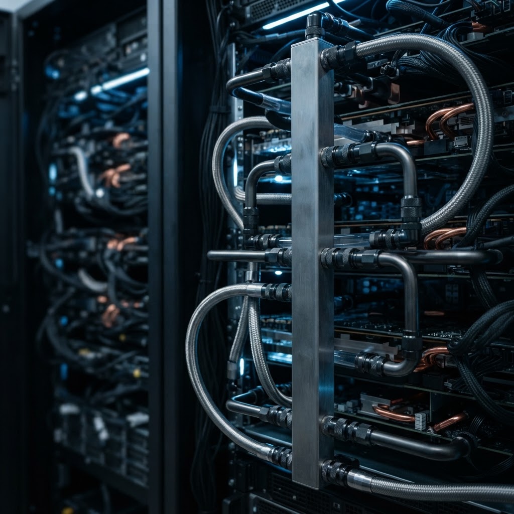
Designed from the slab up for GB300 today and Vera Rubin next
Liquid cooling is in the structural model from Day 1. Structure, cooling and power are sized for three GPU generations, with no retrofit through 2030.
Design once, build many
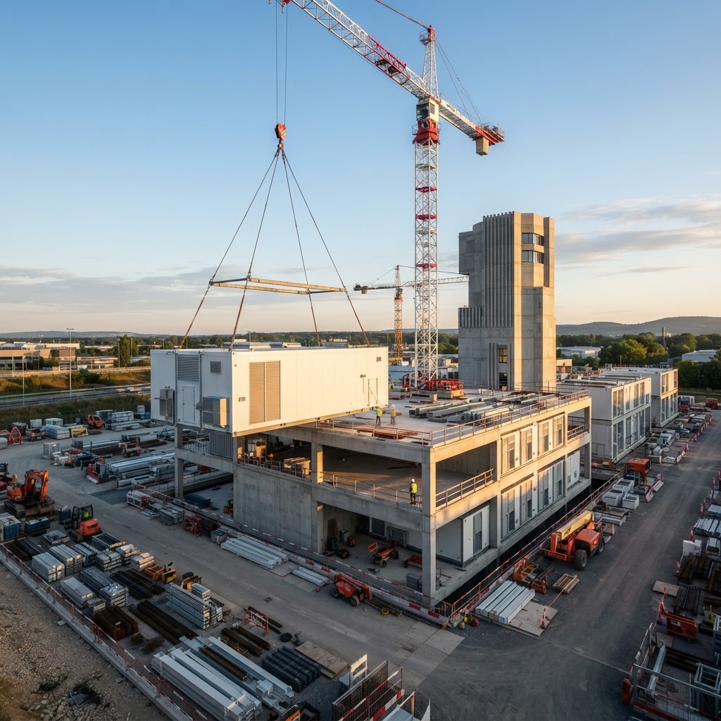
One standard pod scales to a floor and a floor scales to a building. The same template delivers G+5, G+6 and G+7 formats, so a new site starts with a proven design and a qualified supply chain.
Sized to GPU generation and tenant ramp. Fault isolation (N+2C / N+C+M) stays inside one pod.
9–10 pods on one repeatable template, scaling linearly.
G+5 to G+7, with height and floor count set by the site.
About 40% faster deployment than conventional builds. Comparison indicative, from design start to first pod RFS.
Let's build your next campus together
Speak with our team about build-to-suit or colocation capacity.
Contact Us